 RSI Motors
RSI Motors
RSI Motors
Choosing an Industrial Gear Motor is rarely as simple as comparing horsepower and price. The correct unit must match the machine, working cycle, load behavior, and operating environment. A conveyor carrying uneven boxes needs different protection from a mixer handling continuous resistance. Small details matter.
Start with the required output torque, speed, and gearbox ratio. Check acceleration, stopping frequency, shock loads, and daily running hours. A motor that works on paper may still overheat during repeated starts. Service factor deserves careful attention, not casual approval. Mounting position, shaft direction, brake requirements, and available space also influence the final choice.
Look beyond the nameplate. Review efficiency data, thermal limits, noise ratings, sealing levels, lubrication methods, and replacement parts. Dust, washdown water, heat, and corrosive chemicals can shorten service life quickly. Ask manufacturers for tested performance curves and clear warranty terms. Reliable suppliers should explain their calculations instead of offering a generic recommendation.
Field experience teaches another lesson. The cheapest gearbox can become expensive after several unplanned stoppages. Yet oversizing is not automatically safer; it may increase purchase cost, energy use, and starting stress. I have seen specifications change after measuring the real load, rather than trusting an estimated figure. That step is easy to overlook.
Use recognized technical standards and confirm local installation requirements with qualified professionals. Record the decision, including assumptions and operating limits. Recheck those assumptions when production changes. A thoughtful selection process protects equipment, operators, and long-term operating budgets. There is no universal best motor. The best choice is the one supported by evidence, suitable margins, and honest review.
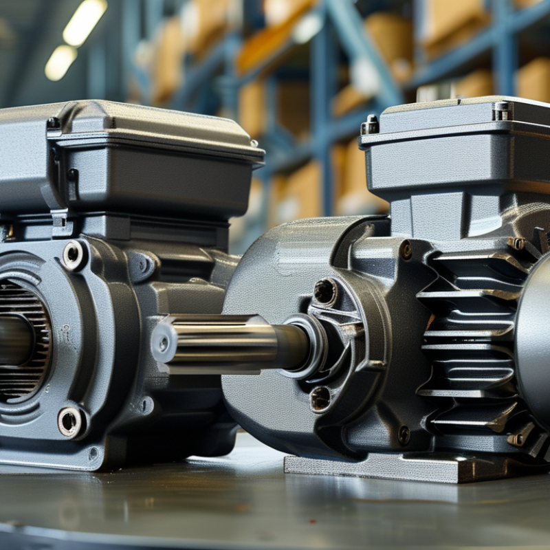
2026 How to Choose an Industrial Gear Motor?
An industrial gear motor combines an electric motor with a gearbox. The motor creates rotational force. The gearbox reduces speed and increases output torque. For example, a 1,450 rpm motor with a 29:1 ratio may deliver approximately 50 rpm. Actual speed changes with load and slip. Helical gears suit efficient conveyors and mixers. Worm gears offer compact, high-ratio transmission, but usually lose more energy as heat. Planetary designs handle high torque in limited spaces.
The gearbox transfers torque through meshing gears, shafts, bearings, and seals. Lubricant protects the tooth surfaces and carries away heat. A poor oil level can turn a quiet reducer into a hot, noisy machine. The International Energy Agency reports that electric motor systems use about 46% of global electricity. The U.S. Department of Energy also identifies motor systems as major industrial energy users. These figures make efficiency more than a purchasing detail. Check rated torque, duty cycle, starting load, ambient temperature, and required output speed. Selecting only by horsepower is a common mistake.
Tips: Measure the real load, not the estimated load. Leave thermal capacity for peaks. Ask for efficiency data at your operating point. Confirm the mounting position and shaft dimensions. Inspect oil, vibration, and temperature during commissioning. A gear motor can look correctly sized yet fail early under repeated shock loads. I have seen calculations miss this detail. Small assumptions matter.
| Gear Motor Type | How It Works | Typical Output Speed | Typical Efficiency | Typical Torque Range | Main Advantages | Common Industrial Uses |
|---|---|---|---|---|---|---|
| Helical Gear Motor | Helical teeth engage gradually, transmitting motor power through parallel or coaxial shafts with low vibration. | Approximately 15–300 rpm | 90–97% | About 20–20,000 N·m | High efficiency, quiet operation, good continuous-duty performance, and compact coaxial designs. | Conveyors, packaging equipment, pumps, mixers, material-handling systems, and production lines. |
| Parallel-Shaft Gear Motor | Helical or spur gear stages transmit power between parallel input and output shafts. | Approximately 10–250 rpm | 93–98% | About 100–30,000 N·m | High torque density, efficient power transmission, and a slim installation profile. | Belt conveyors, roller conveyors, elevators, crushers, feeders, and bulk-material systems. |
| Bevel-Helical Gear Motor | A bevel gear stage changes the direction of rotation, while helical stages provide efficient speed reduction. | Approximately 10–300 rpm | 92–97% | About 100–50,000 N·m | High efficiency, strong radial and axial load capability, and flexible right-angle mounting. | Heavy conveyors, mixers, hoists, processing machinery, pallet systems, and bulk handling. |
| Worm Gear Motor | A worm screw drives a toothed wheel at a right angle, producing high reduction in a compact housing. | Approximately 5–150 rpm | 50–90%, depending on reduction ratio and design | About 10–5,000 N·m | Compact right-angle arrangement, high reduction ratios, low cost, and possible self-locking at selected ratios. | Gates, small conveyors, positioning systems, packaging machinery, lifts, and adjustment mechanisms. |
| Planetary Gear Motor | Multiple planet gears share the load between a sun gear and an internal ring gear. | Approximately 10–500 rpm | 90–98% | About 50–100,000 N·m | Very high torque density, low backlash options, compact dimensions, and excellent load sharing. | Robotics, servo systems, indexing equipment, heavy automation, mobile machinery, and high-precision drives. |
| Spur Gear Motor | Straight-cut teeth transfer motion between parallel shafts with simple, direct engagement. | Approximately 20–500 rpm | 85–95% | About 1–2,000 N·m | Simple construction, economical maintenance, and suitability for moderate loads and intermittent operation. | Small conveyors, feeders, actuators, vending equipment, machine tools, and light automation. |
| Selection Dimension | What to Determine | Why It Matters | Practical Guidance |
|---|---|---|---|
| Required Output Torque | Continuous torque, peak torque, starting torque, and shock loads. | Insufficient torque can cause stalling, overheating, or premature gear damage. | Select a service factor appropriate for load variation, usually higher for shock or frequent starts. |
| Output Speed | The required shaft speed in revolutions per minute. | Speed determines production rate, conveyor velocity, and machine cycle time. | Use the reduction ratio relationship: output speed is approximately motor speed divided by gearbox ratio. |
| Motor Power | Required mechanical power, commonly specified in kilowatts. | Power links torque and speed and helps prevent undersizing. | Use the approximate relationship: power in kW = torque in N·m × speed in rpm ÷ 9,550, before allowing for losses. |
| Duty Cycle | Operating hours, starts per hour, reversing frequency, and load profile. | Thermal stress and mechanical fatigue vary significantly between intermittent and continuous operation. | Match the motor insulation, thermal rating, and gearbox service factor to the actual operating cycle. |
| Mounting and Shaft Arrangement | Foot, flange, shaft-mounted, inline, parallel-shaft, or right-angle configuration. | The arrangement must fit the machine envelope and transmit loads safely. | Confirm shaft diameter, mounting dimensions, rotation direction, overhung load, and axial load limits. |
| Operating Environment | Dust, water, chemicals, ambient temperature, washdown, altitude, and hazardous-area requirements. | Environmental exposure affects sealing, lubrication, corrosion resistance, cooling, and electrical safety. | Select the appropriate enclosure rating, corrosion protection, lubricant, and temperature capability. |
| Power Supply and Control | Voltage, phase, frequency, starting method, variable-frequency drive use, and braking requirements. | Electrical compatibility affects starting torque, speed control, energy consumption, and motor life. | Verify rated voltage, full-load current, insulation system, inverter compatibility, and required protection devices. |
| Efficiency and Total Cost | Gearbox efficiency, motor efficiency, energy price, maintenance, and expected service life. | Energy use over many operating hours can exceed the initial purchase cost. | Compare lifetime operating cost rather than evaluating purchase price alone, especially for continuous-duty equipment. |
Note: The performance ranges shown are typical engineering ranges. Actual values depend on gear ratio, motor power, lubrication, duty cycle, mounting position, thermal conditions, and the specific mechanical design.
: Helical gearboxes provide steady torque and good efficiency. They suit conveyors, mixers, and pumps. Check wet aggregate, startup load, heat, and sealing. Catalog figures can mislead.
Choose a bevel gearbox when power must turn through a right angle. It supports compact machine layouts. Confirm shaft direction and available mounting space before ordering.
Worm gearboxes offer high reduction in a simple housing. Sliding contact can create more heat and energy loss. Good reduction, higher heat.
Planetary gearboxes handle high torque inside a smaller housing. They may cost more and require more demanding maintenance. Check whether compact size justifies those costs.
Measure startup torque, running torque, and peak torque separately. Compare output torque after efficiency losses. Check real overloads, not ideal test conditions. Leave room for uncertainty.
Record operating hours, starts per hour, load changes, and stopping periods. Continuous operation needs different thermal planning from intermittent indexing. Frequent reversals may require extra capacity.
Heat, dust, moisture, altitude, and mounting position can change motor performance. Record current, voltage, speed, and surface temperature during a typical shift. A clean test room proves little.
Check overload protection, braking, enclosure rating, guards, wiring, and regional conformity documents. Also inspect oil access, seals, bearings, backlash, vibration, and lubricant condition. Purchase price is incomplete.Include electricity, installation labor, spare parts, downtime, and disposal costs. Request drawings, load calculations, training details, warranty terms, and written response times. Support may weaken after delivery.
Choosing the right Industrial Gear Motor is essential for achieving reliable, efficient, and cost-effective performance in industrial equipment. This guide explains how an Industrial Gear Motor transfers power through a motor and gearbox to produce controlled speed and increased torque. It also outlines how to calculate the required torque, output speed, and power based on load characteristics, starting conditions, and operating requirements. Selecting the appropriate gearbox type depends on factors such as space limitations, transmission ratio, noise levels, shock loads, and application demands.
The guide also examines motor efficiency, duty cycle, ambient temperature, dust, moisture, vibration, and other operating conditions that may affect service life. In addition, it highlights the importance of safety features, simple maintenance, total ownership cost, spare parts availability, technical assistance, and supplier reliability. By evaluating these factors together, users can select a gear motor that delivers stable performance, minimizes downtime, and supports long-term industrial productivity.
